Variable air volume controllers
|
47
T
VAV-Compact
Functions
Room pressure ratio
In a parallel connection, the two VAV units are operated
independently of one another with a common reference
signal. The operating volumetric flows of the supply and
exhaust air units must be set according to the required room
pressure ratio.
The supply and exhaust air controllers work independently
of one another, i.e. if a fault occurs in the supply or exhaust
air system, the room pressure ratio is impaired for technical
reasons. In the worst case, the unit tolerances may be
accumulated. This circumstance must be taken into account
by the project planning engineer.
When are parallel connections used?
y
y
If air volume controllers operate with parallel supply
and exhaust air (controlled by a common reference
variable)
y
y
If the supply and exhaust air devices have different
sizes and different minimum and maximum volumetric
flow settings
y
y
If constant differential control is active between the
supply and exhaust air
y
y
In systems with several supply and exhaust air devices
y
y
In circulating air systems for airtight rooms.
Operating volumetric flow settings
The max and min values used for the required volumetric
flow must be set on each VAV controller.
CAV application
In constant air volume applications, operating mode
control (CLOSED / min etc.) is set on both controllers.
Setting if the room pressure ratio is balanced
Owing to the proportional assignment of the reference
signal to the value ranges for max and min , it is possible
to operate VAV units with different nominal widths and
differentiated ranges parallel to one another.
Setting if the room pressure ratio is unbalanced
The operating volumetric flows of the supply and exhaust
air units must be set according to the difference:
y
y
Positive pressure ratio in the room Supply air volume >
exhaust air volume
y
y
Negative pressure ratio in the room Exhaust air vol-
ume > supply air volume
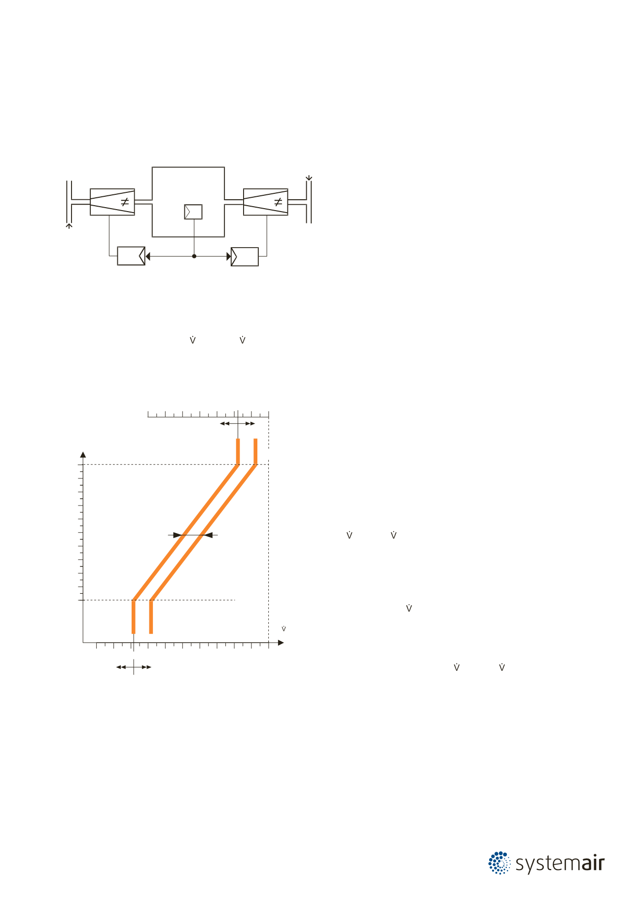
Principle:
The reference signal of the temperature controller is
connected in a parallel circuit with the reference value
inputs of the supply and exhaust air controllers. The
operating volumetric flows max and min are set on
both controllers.
For connection diagram, see page 39-42
Parallel connection
SUPPLY
SUP.
EXH.
Room
EXHAUST
Volumetric flow
[% nom ]
0
100
10
30 40 50 60 70 80 90
100%
30 40 50 60 70 80 90
[V]
10
0
1
2
3
4
5
6
7
8
9
min
min
max
max
20
Constant
supply /
exhaustair
difference
Volumetric flow
actual value signal U 5
Example with mode:
0 … 10 V


