145
Ground indicator - use of L, T and X connectors
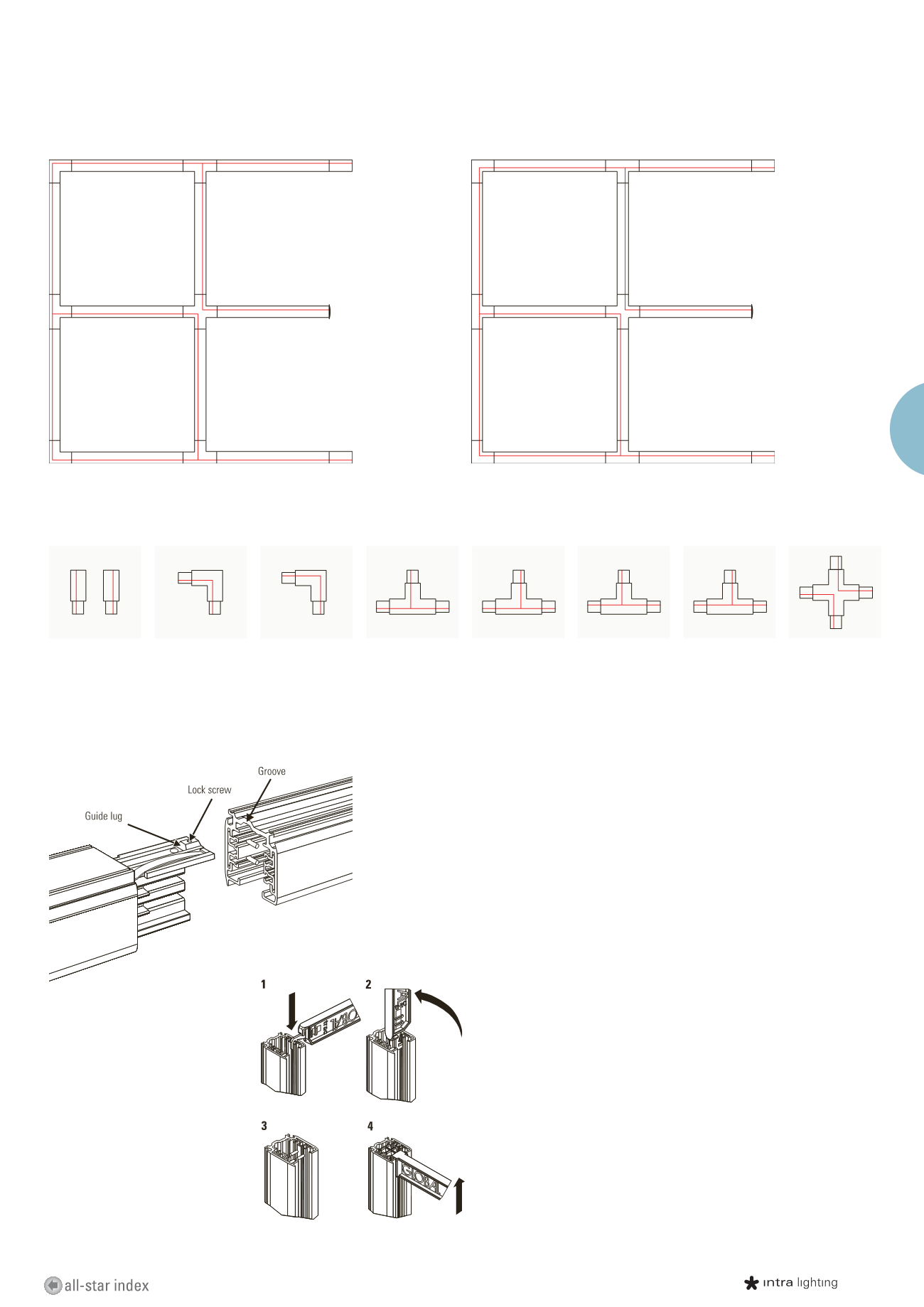
Connectors preview
Connecting
Installation of the connector parts
When installing the connector parts to
the track, it is necessary to ensure that the
guide lug enters the groove in the base of
the track. The fastening of the connectors
to the track is secured by the lock screws.
The earth conductor is on the same side as ridge of the track. During selection of power feed and LTX connectors take care that the
continuous line is not interrupted.
How to cut the track?
Lighting tracks are supplied
in standard lengths. They are also easy to
cut to the required length with a hacksaw
or with a circular saw designed for
aluminium cutting.
After the track has been cut, the conductors
have to be bent at an angle of 90 degrees.
Use the bending tool XTSV 12 for bending.
The conductors can be measured and
finished with the plastic gauge at the other
end of the tool.
The bent conductors are at the right
distance from the end of the track when
the plastic gauge does not protrude but lies
flush with the track end.
XTS 11, 12
End power feed:
right (XTS 11)
left (XTS 12)
Floor view - red line indicates ridge of the track
Floor view - red line indicates ridge of the track
XTS 34
L - joint internal
XTS 35
L - joint external
XTS 39
T - joint external
XTS 36
T - joint external
XTS 37
T - joint internal
XTS 40
T - joint internal
XTS 38
X - connector
XTS 38
XTS 38
XTS 36
XTS 40
XTS 11
XTS 39
XTS 39
XTS 37
XTS 37
XTS 35
XTS 35
XTS 34
XTS 34
XTS 12
SPOTS
TRACKS


