Variable air volume controllers
|
61
Electrical installation
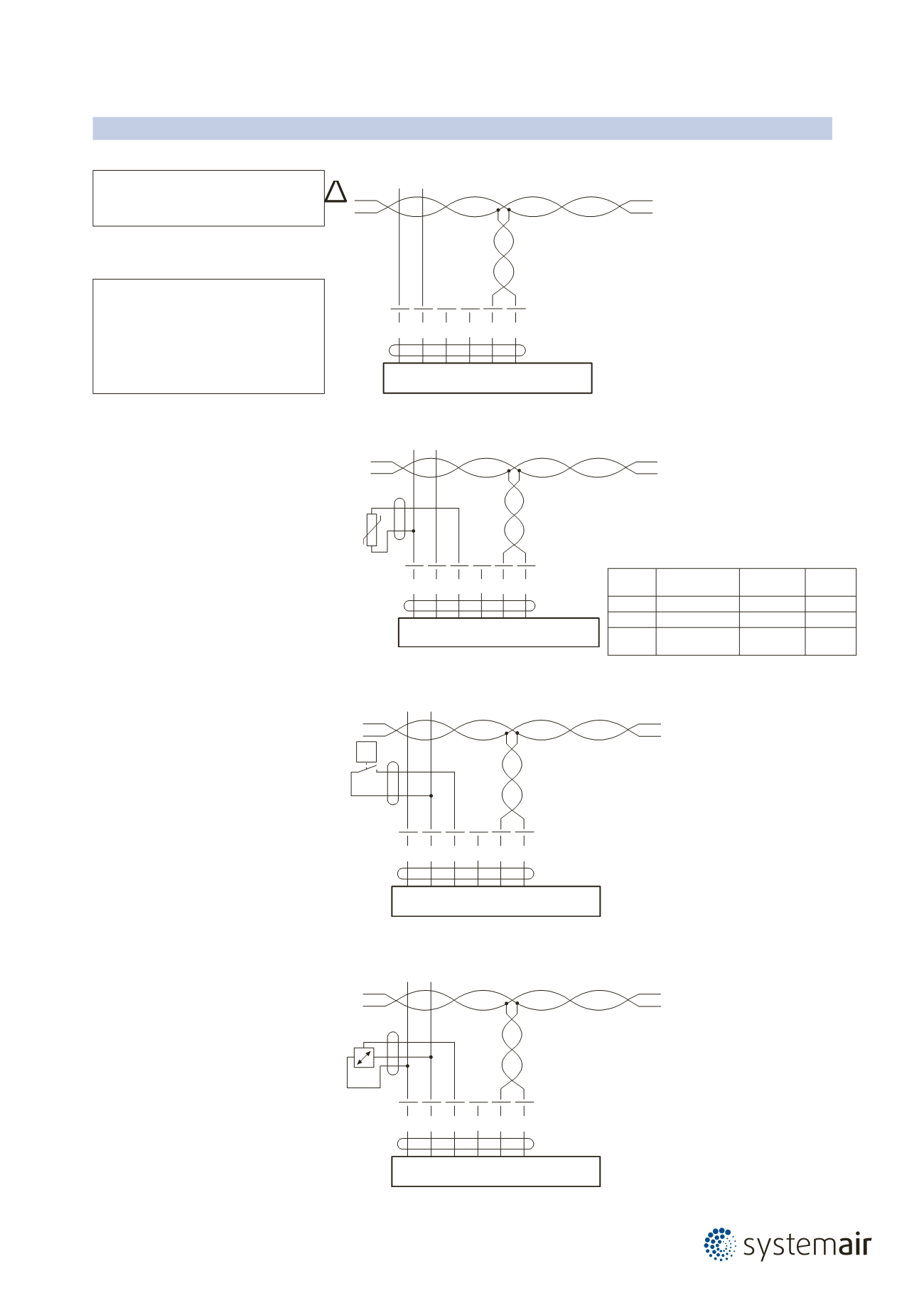
Connection diagram for cable layout
Connection without sensor
Connection with passive sensor, e.g. Pt1000, Ni1000, NTC
Connection with switching contact, e.g. ∆p-monitor
Requirements for switching contact:
The switching contact must be able to
accurately switch a current of
16 mA at 24 V.
Connection with active sensor, e.g. 0 ... 10 V @ 0 ... 50°C
Possible input voltage range:
0 ... 32 V (resolution 30 mV)
Note
Connection via safety isolating transformer.
!
5 6 7
3
2
1
MFT
T
~
+
–
T
~
+
–
D
+
D
–
Modbus (RS-485)
∆p
5 6 7
3
2
1
MFT
T
~
+
–
T
~
+
–
D
+
D
–
Modbus (RS-485)
5 6 7
3
2
1
MFT
D
+
D
–
T
~
+
–
T
~
+
–
Modbus (RS-485)
5 6 7
3
2
1
MFT
T
~
+
–
T
~
+
–
D
+
D
–
Modbus (RS-485)
Note
Modbus signal assignment:
C 1 = D– = A
C 2 = D+ = B
Power supply and communication are not
galvanically isolated.
Interconnect ground signal of the devices.
Sensor
Temperature
range
Resistance
range
Resolution
Ni1000
–28 ... +98°C 850 ... 1600 � 1 �
PT1000
–35 ... +155°C 850 ... 1600 � 1 �
NTC
–10 ... +160°C
(depending on type)
200 ... 50 k� 1 �


